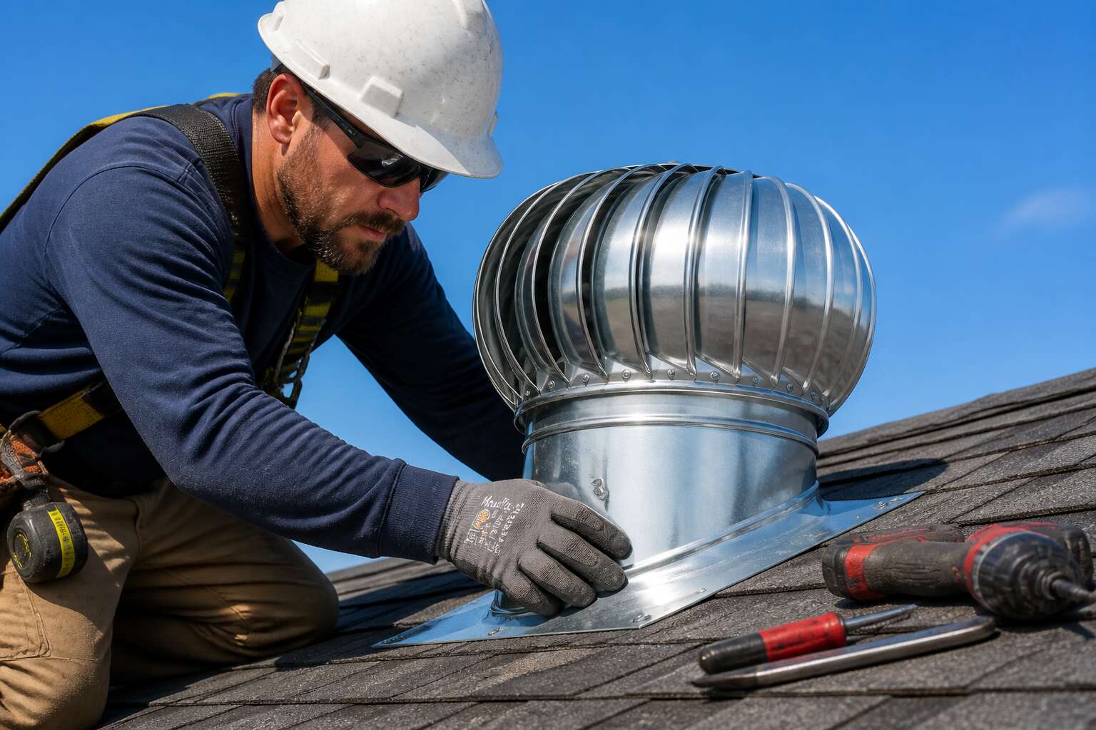
Essential Principles of Ventilation System Design
Why Attic Ventilation Matters
An unventilated roof cavity in a South African summer can climb past 70°C, forcing cooling systems to work overtime well before midday. Proper roof ventilators construction is therefore a matter of necessity. The essential principles of ventilation system design are straightforward, yet often misunderstood.
Air requires a clear path. Intake vents at the eaves admit cooler air while exhaust vents near the ridge release superheated air. This convection cycle depends on balanced net free area; excess intake with insufficient exhaust causes stagnation. For South African homes, design must also account for high summer solar gain and winter moisture loads.
- Intake and exhaust vents aligned with prevailing wind patterns
- Equivalent net free area between lower and upper openings
- Unobstructed air channels above insulation battens
Why attic ventilation matters extends beyond temperature control. Moisture from cooking, bathing, and daily living condenses on the underside of the roof deck, instigating rot and corrosion. Consistent airflow preserves the integrity of the entire roof ventilators construction, protecting trusses and sheathing from premature decay.
Understanding Airflow Dynamics
Air moves only under duress. I have watched it stall in cavities that appeared perfectly vented on paper. It will not climb toward the ridge without a pressure gradient forcing it upward. Understanding airflow dynamics means accepting that movement is governed by physics alone. In a typical South African roof, thermal buoyancy and wind-driven negative pressure operate simultaneously, each exerting force on the trapped air. Stratification remains the persistent problem: superheated air collects against the ridge while cooler air gathers along the eaves, unless the geometry of the roof ventilators construction actively disrupts that separation.
Factors governing this behaviour include:
- The depth of the cavity between insulation and the roof deck
- Internal obstructions such as plumbing stacks, wiring runs, or collar ties
- The pitch angle of the roof, which dictates how wind accelerates or stalls
Alter one variable and the flow pattern shifts. Anticipating these deviations is the discipline of roof ventilators construction.
Calculating Ventilation Requirements
A 30 degree day can turn a poorly designed roof cavity into a 60 degree furnace. That heat does not wait for permission! It radiates downward through ceilings. Good roof ventilators construction starts with honest calculations, not optimistic guesses. You need the net free area of each vent, the pitch line, and the intended airflow direction.
Calculate the required vent area using the attic floor area. For South African conditions, aim for a ratio of 1:150 for roof ventilators construction, then verify against local wind patterns. The numbers shift when you add gable ends or continuous ridge vents.
- Measure the horizontal roof footprint, not the roof slope area.
- Subtract obstructions such as skylights or chimneys.
- Divide the total by 150 to get the minimum ventilation area.
Then balance intake and exhaust. A ridge vent without matching eaves fails entirely. I have seen the math break because someone doubled the exhaust side while shrinking the soffit vents.
Selecting Materials and Components
Choosing Between Static and Powered Ventilators
Choosing components for roof ventilators construction begins with the material itself. In coastal South African towns, galvanised steel proves its worth, while aluminium stays light on the structure and copper offers longevity at a premium. I find that fasteners matter equally; stainless screws prevent rust streaks that disfigure rooflines.
- Galvanised steel for corrosive air
- Aluminium for weight sensitive frames
- Copper for heritage architecture
Static ventilators work with thermal buoyancy and prevailing winds, requiring no wiring and no maintenance besides occasional cleaning. Powered ventilators bring controlled extraction, useful for large industrial spans or windowless rooms. In roof ventilators construction, the decision hinges on the building’s daily rhythm, not solely on weather patterns.
A silent static unit suits a sloped home roof. A powered unit earns its place where heat pools stubbornly. Selecting between them depends on inspecting the actual structure, rather than relying on product brochures.
Durability and Weather Resistance
South Africa’s high UV index and coastal salt spray test every component of roof ventilators construction. In Durban’s humid air or the Karoo’s dry heat, materials age differently. Galvanised steel can fail within five years when paired with the wrong fasteners, while aluminium stands firm for decades. The choice of alloy, coating thickness, and sealant determines whether a ventilator survives its first decade.
Consider the parts that face direct weather exposure:
– Roof ventilator bases should use hot-dip galvanised steel with a minimum 450 g/m² zinc coating
– Fasteners must be marine grade 316 stainless steel, not the cheaper 304 grade
– Sealing collars need EPDM rubber or butyl tape, not acrylic sealants that crack under UV
Each component works together. A robust housing with brittle seals fails as surely as a thin housing with perfect seals. The junctions between components define the lifespan of any roof ventilators construction.
Flashing and Sealing Solutions
Flashing and sealing determine where a ventilator ends and the roof begins. The flashing profile must mirror the roof sheeting’s ribs, whether IBR or tile. A rigid aluminium flashing, folded to match the contour, creates a watertight transition that no mastic alone can achieve.
The assembly sequence for roof ventilators construction rewards patience, and I have watched many installers rush this step:
- Fit the flashing skirt over the opening, pressing it into the sheeting’s valleys.
- Lay a continuous bead of polyurethane sealant along the flashing’s upper flange.
- Lower the ventilator base and torque fasteners evenly, allowing the seal to compress without squeezing out entirely.
Counter-flashing adds a second layer over the first, a principle that anchors sound roof ventilators construction. The overlap intercepts wind-driven rain before it reaches the seal. This matters in Highveld thunderstorms, where rain runs uphill in sheets. Without this layering, a ventilator leaks quietly for years.
Insulation Considerations
On a Highveld summer afternoon, a roof surface exceeds 70°C. Galvanised steel resists coastal salt, while aluminium endures the Highveld’s ultraviolet radiation with less maintenance. Selecting materials for roof ventilators construction requires attention to that heat and salt. Each component, from the base flange to the insulation blanket, performs a thermal role.
Insulation considerations affect how a ventilator behaves across a day. A steel shaft conducts heat readily; a polymer sleeve interrupts that transfer. Fibreglass batting absorbs sound and cold, but closed-cell foam resists moisture that Highveld thunderstorms throw sideways!
- The metal gauge must match wind loading, not price.
- A thermal break between the roof deck and the ventilator throat reduces heat flow.
- Insulation with a vapour barrier facing the warm side controls condensation.
The interplay of metal, foam, and fasteners determines whether condensation forms. In my experience, roof ventilators construction succeeds when each layer performs its function.
Step-by-Step Installation Guide
Preparing the Roof Surface
Nobody ever walked onto a roof and said, “I wish this was dirtier!” For roof ventilators construction, a clean surface decides everything. Start by stripping away old caulk, leaves, and bird droppings. Then run your hand over the sheathing. Inconsistent spots mean trouble. Use a straightedge to check for warping. The deck must be dry before any flashing touches it.
Here is a simple order of operations:
- Remove all loose material.
- Repair damaged wood.
- Primer the area around the hole.
These steps take fifteen minutes. Skipping them takes a second roof visit.
Positioning and Marking Cutouts
Positioning the cutout is where roof ventilators construction demands precision. Do not trust your eye. Measure from the ridge and the nearest gable end, then transfer those numbers to the sheathing. A chalk line gives you a straight reference across the deck. We have seen many crooked ventilators from skipped measurements.
Use the manufacturer’s template to trace the opening. Mark the corners clearly. Check the orientation against the roof slope. That small step saves an afternoon! For a neat process, follow this order:
- Verify the rafter bay is clear
- Set the template centre line
- Trace with a fine marker
Finally, cut along the inside of your line. Remember, the saw blade removes material, so leave that edge intact for a snug fit.
Cutting Techniques for Different Roof Types
Cutting through a roof is where the nerves kick in, and rightly so. A concrete tile snaps differently than a pressed metal sheet. Roof ventilators construction requires matching the cutting technique to the material. On clay or concrete tiles, an angle grinder with a diamond blade scores the glaze cleanly. Do not lean on it, or you will chip the tile. For corrugated IBR sheeting, a nibbler beats a grinder. It leaves a smooth edge without flinging sparks into the insulation. Asphalt shingles call for a sharp utility knife and a straightedge. Score the back first to prevent tearing.
This sequence holds for most roofs:
1. Cut from the underside when possible.
2. Use the correct blade for the material.
3. Test the fit before flashing.
Metal roofs demand steady hands. A jigsaw with a fine-tooth blade cuts IBR cleanly, but mark your line with a felt tip pen. Chalk washes away before the first raindrop. Roof ventilators construction rewards patience here. A jagged edge is a leak waiting for an invitation.
Securing the Ventilator Base
One in four roof leaks starts at the ventilator base, not the flashing. That is why securing this part matters more than any other step in roof ventilators construction. The base must sit dead level on the roof deck, even if the roof itself is slightly uneven.
Lower the base over the cutout and check the fit. On a metal roof, the base should hug the profile tightly. I usually press down firmly along the edges to bed the gasket into place. Then I work around the flange with a socket driver, not a drill, to control torque.
- Run a bead of polyurethane sealant along the underside of the base.
- Insert a screw through each pre-drilled hole, starting at opposite corners.
- Snug each fastener gently, then do a second pass to set them fully.
After that, check for any rocking or flex. A stable base supports the rest of the assembly correctly.
Installing Flashing for Waterproofing
The flashing is not an ornament. It is the final seal between the ventilator and the roof, and in roof ventilators construction, this layer decides how long the whole assembly stays dry. I always start with the lowest side of the opening, letting each strip overlap the one before it, like pages falling in sequence.
After the base is fixed, I cut the flashing to overhang the flange by at least 25 mm. Then I work it around the profile with a clean rag, pushing the metal into the contour. The order below has never failed me in the field:
- Position the first strip at the bottom edge, overlapping the flange fully.
- Press the flashing into the sealant with a wooden block, not a hammer.
- Move upward in rows, each strip overlapping the previous one by 50 mm.
- Fasten the flashing edge with screws spaced 75 mm apart.
Each overlap must face the direction of water run-off, which is a simple thing to overlook. When done correctly, the flashing becomes a continuous skin, not a patch. And that skin is what carries the load of years.
Avoiding Common Installation Mistakes
Incorrect Placement and Spacing
Placement errors account for many underperforming systems. The position of each ventilator dictates how effectively air moves. A unit placed too close to the ridge short-circuits the airflow. I have seen this happen often on South African homes with steep pitches. Spacing is equally problematic. Vents set too far apart leave pockets of stale air that never reach an exhaust point. Vents set too close create turbulence that reduces suction. Both mistakes stem from hasty measuring.
The common mistakes are simple to overlook:
- Ventilators crammed into one roof plane.
- Gaps exceeding the recommended span.
- Units placed near obstructions such as chimneys or parapets.
Each error compels the system to work harder for less result. The roof’s natural contours and existing structures get ignored. Roof ventilators construction demands equal attention to the roof area and the airflow path. Poor placement manifests as uneven temperatures and higher energy bills. That is a frustrating outcome for any installer!
Overlooking Local Building Codes
In South Africa, roof ventilators construction must respect the National Building Regulations, particularly SANS 10400. Many installers treat municipal approval as a suggestion rather than a requirement. That is a costly assumption. A neighbour’s complaint or an insurance assessor’s sharp eye can undo weeks of work.
Local bylaws vary between municipalities. What passes in Johannesburg may fail in Cape Town. Common requirements include:
- Engineered drawings from a certified draughtsperson.
- Written consent from a homeowners’ association.
- A site inspection before the roofing work begins.
Ignoring these rules leaves homeowners exposed to liability. I have watched perfectly sound installations get stripped from roofs because the paperwork never existed. The absence of an approval record becomes visible only at the worst moment. A roof leak, a fire claim, a property sale. Roof ventilators construction without the correct municipal sign-off turns a functional upgrade into a legal complication.
Ignoring Roof Pitch Compatibility
A ventilator rated for a 35 degree pitch will fail on a 15 degree roof. The base cannot sit flush, the flashing buckles, and water finds the gap. Roof ventilators construction requires matching the unit to the actual slope, not the roof you assume is there.
South African roof pitches vary wildly, from Cape Town’s flat concrete slabs to Durban’s steep thatch alternatives. That variation changes how the collar must be cut, how the base is bedded, and how the flashing is dressed. A rigid base built for a steep pitch leaves a wedge-shaped opening on a shallow roof. That opening collects debris and holds water against the flashing membrane.
- Measure the pitch with a digital inclinometer, not a guess.
- Check the manufacturer’s compatibility range before cutting.
- Use adjustable bases only within their certified limits.
Roof ventilators construction fails most often from a mismatched angle. The fix costs nothing at planning and everything after the cut.
Maintenance and Performance Optimization
Cleaning and Debris Removal
Neglect undermines any ventilation system. Over time, leaves, dust, and the persistent detritus of the Highveld accumulate on screens and within channels. This buildup restricts airflow, forcing the unit to strain in its task. Common culprits include:
- Pine needles and oak leaves
- Windblown sand from the Karoo regions
- Fibrous nesting material from birds
Cleaning must be deliberate. Inspect the exterior housing each quarter, and clear the mesh with a soft brush. Then consider the internal blades. A residue of grime and pollen unbalances them, accelerating bearing wear. For roof ventilators construction, a routine that includes wiping down blades and checking motor vents prevents premature failure.
Inspecting Seals and Flashing
A single cracked seal undoes years of careful roof ventilators construction. Water finds the gap you ignored. It travels along the flashing, seeps under the base, and stains the ceiling below before you ever notice.
Inspect the seals and flashing every six months, ideally after the rainy season ends. This ritual protects the entire roof ventilators construction. Run a finger along the sealant bead. It should feel firm, not tacky or crumbling. Check the flashing edges for separation from the roof surface. A gap of even two millimetres invites trouble.
Pay attention to these specific points:
- The rubber gasket around the ventilator base. UV rays from the African sun degrade it over time. If it feels brittle or shows hairline cracks, replace it immediately.
- The flashing joints at the corners. These are the first places where movement shows.
- The sealant where the flashing meets the roof. Cracks running parallel to the bead mean aging. Vertical cracks mean the base is shifting.
Upgrading to Smart Ventilation
Maintenance keeps a system reliable, but optimization is where roof ventilators construction proves its full value. Once your seals and flashing are sound, look at how the ventilator actually behaves through a Highveld summer and a Cape winter. I have watched static units lose efficiency simply because nobody adjusted them seasonally. Smart ventilation upgrades add sensors that measure temperature and humidity inside the roof cavity. These devices adjust airflow automatically, removing the guesswork from static timers. This matters in South Africa’s mixed climates. Consistent air movement protects both the structure and the insulation. For homeowners thinking about an upgrade, certain features carry real weight:
1. Remote monitoring through smartphone apps
2. Humidity triggers that activate fans before condensation forms
3. Temperature differentials that open vents only when useful
Each feature adds control, so a passive system becomes active in preserving the building.
Seasonal Checks
On the Highveld, July mornings hit differently than February afternoons. That contrast shows how roof ventilators construction responds. I have watched static units lose efficiency because nobody adjusted them seasonally.
Seasonal checks happen when the weather shifts. The first test comes under the noonday sun, measuring whether airflow keeps pace with heat. The second arrives with the first cold front, when humidity creeps into the roof cavity.
The variations across two seasons demand attention:
- Dust from summer storms settles on sensor lenses.
- Humidity triggers need calibration before winter condensation.
- Temperature differentials lose alignment with cavity conditions.
These faults build up over months, often unnoticed.

0 Comments